|
| <-- Back to Previous Page | TOC | Next Section --> |
Chapter 4: The Synthesis of Sound by ComputerSection 4.5: Amplitude Modulation |
||
|
||
|
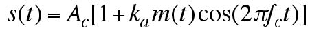
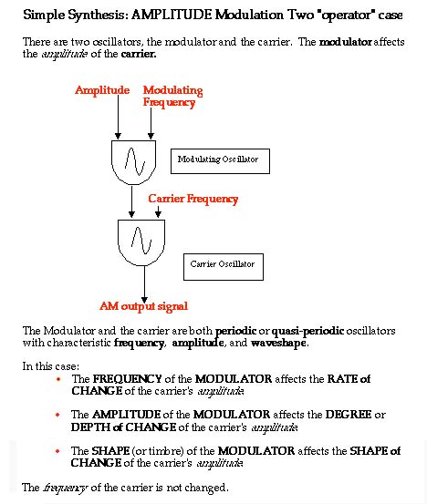
Applet 4.9 shows what happens, in the case of frequency modulation, if the modulating signal is low frequency. In that case, we’ll hear something like vibrato (a regular change in frequency, or perceived pitch). We can also modulate amplitude in this way (tremolo), or even formant frequencies if we want. Low-frequency modulations (that is, modulators that themselves are low-frequency signals) can produce interesting sonic effects. But for making really complex sounds, we are generally interested in high-frequency modulation. We take two audio frequency signals and multiply them together. More precisely, we start with a carrier oscillator and attach a modulating oscillator to modify and distort the signal that the carrier oscillator puts out. The output of the carrier oscillator can include its original signal and the sidebands or added spectra that are generated by the modulation process. Amplitude ModulationFigure 4.13 shows how we might construct a computer music instrument to do amplitude modulation. The two half-ovals are often called unit generators, and they refer to some software device like an oscillator, a mixer, a filter, or an envelope generator that has inputs and outputs and makes and transforms digital signals.
Figure 4.13 Amplitude modulation,
two operator case. |
||
|
|
||
 Soundfile 4.18 Low-pass moving filter (modulated by sine) |
A low-pass moving filter that uses a sine wave to control a sweep between 0 Hz and 500 Hz. |
|
|
|
||
|
|
A high-pass moving filter that uses a sine wave to control a sweep between 5,000 Hz and 15,000 Hz. |
|
|
|
||
|
|
A low-pass moving filter that uses a sawtooth wave to control a sweep between 0 Hz and 500 Hz. |
|
|
|
||
|
|
A high-pass moving filter that uses a sawtooth wave to control a sweep between 5,000 Hz and 15,000 Hz. |
|
|
|
||
|
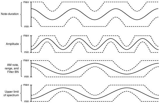
Figure 4.14 James
Tenney’s "Phases," one of the earliest and still most interesting
pieces of computer-assisted composition. The pictures above are his "notes"
for the piece, which constitute a kind of score. |
||
| <-- Back to Previous Page | Next Section --> |
©Burk/Polansky/Repetto/Roberts/Rockmore. All rights reserved.